FSK modem on DSP card
Date: Dec. 2005
This is a homework,
in the digital signal processing specialization direction, in the university.
My task is, to write assembly programs, to an existing DSP card, to implement
an FSK modem. And also is my task, to write a control software to PC, in c
language, under DOS.
The block
diagrams are shown here:
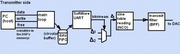
Inside the transmitter, the modulator
is a numerically controlled oscillator. This is simply a lookup table (sine
wave table) reader routine. The reading step between the following samples,
depends on the actual bit value, in a bitstream. An UART implementation makes
the bitstream, from the stored data, in the data FIFO buffer. A main routine
puts the data into the buffer. As transmit filter, i used 127th order FIR
filters. All filters in the project, are the same type.
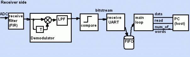
In the receiver, there is a
receiv-filter. This is exactly the same, as the transmit-filter. Other modules
are the inverse of the modules, in the transmitter, exept the demodulator. The
demodulator has a delay. This delay has to have a period time, equal to the
carryer’s period. It can be some other values, but in those cases, the output
DC level will be different.
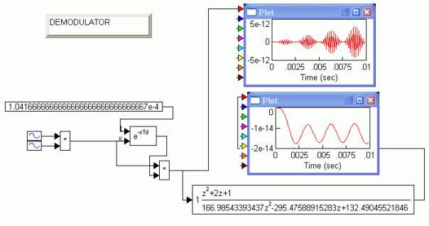
I tried to simulate the demodulator in the
Commsim2001 communications-system simulator-software.
You can
see the output of the multiplier (with some unwanted noises), and the
filtered output, after the LPF. This last one is the original modulator
signal, shifted with a DC level.
I choose a carrier frequency of 2400Hz and a
sample rate of 9600Hz. This two values must be in this relation (1/4). The data
rate is 200bps. Wery slow. The frreqencies of the MARK/SPACE are 2400+/- 600Hz:
1800/3000Hz. The transmitter produces only the mark and the space frequencies,
but not the carryer freq.
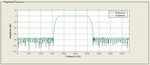
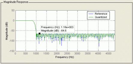
The FIR
filters:
Two
band-pass and a low-pass filter. 127th order raised cosine, equiripple,
non-windowed.
The UARTs are difficult state machines. I have
chosen this UART-solution because it solves the byte and bit detection
problems. These are also in the DSP’s software
The
transmitter and the receiver can run on the same DSP, almost independently. If
somebody wants, he/she can put more channels on the same DSP.
The user
interface:
Here is a
screenshot of the application software:
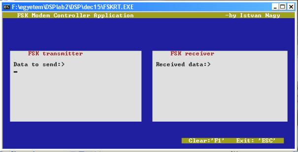
This is a
simple chat program. It uses the DSP card. It writes to/read from the DSP’s
memory, where the handshaking and data variables are.